How Wire Shaping Affects Strength in OEM Components
Strength in an OEM wire component is never just a material question. A part can start with high-strength wire and still fail in service if the shape forces strain into the wrong area, if the bend radius is too tight, or if springback pushes the finished geometry out of tolerance.
That is why wire shaping deserves more attention early in product design. The way wire is bent, wrapped, offset, flattened, or welded changes how loads move through the part. It also changes whether the component will return to its intended shape, hold a repeated fit, and survive cycling over time.
A good design process treats shaping and strength as a matched system. When OEM teams work with a capable wireform manufacturer, they can often improve structural integrity not by choosing the strongest possible wire, but by choosing the right material condition and the right geometry for the job.
Why wire shaping changes component strength
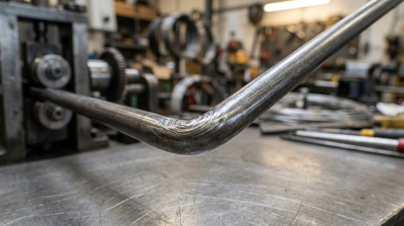
A straight wire and a formed wire made from the same alloy do not behave the same way. Once the wire is bent, strain concentrates at the outside of the bend while compression builds on the inside. That local change matters because service loads rarely spread evenly across a formed part. They tend to collect at corners, offsets, transition points, and contact features.
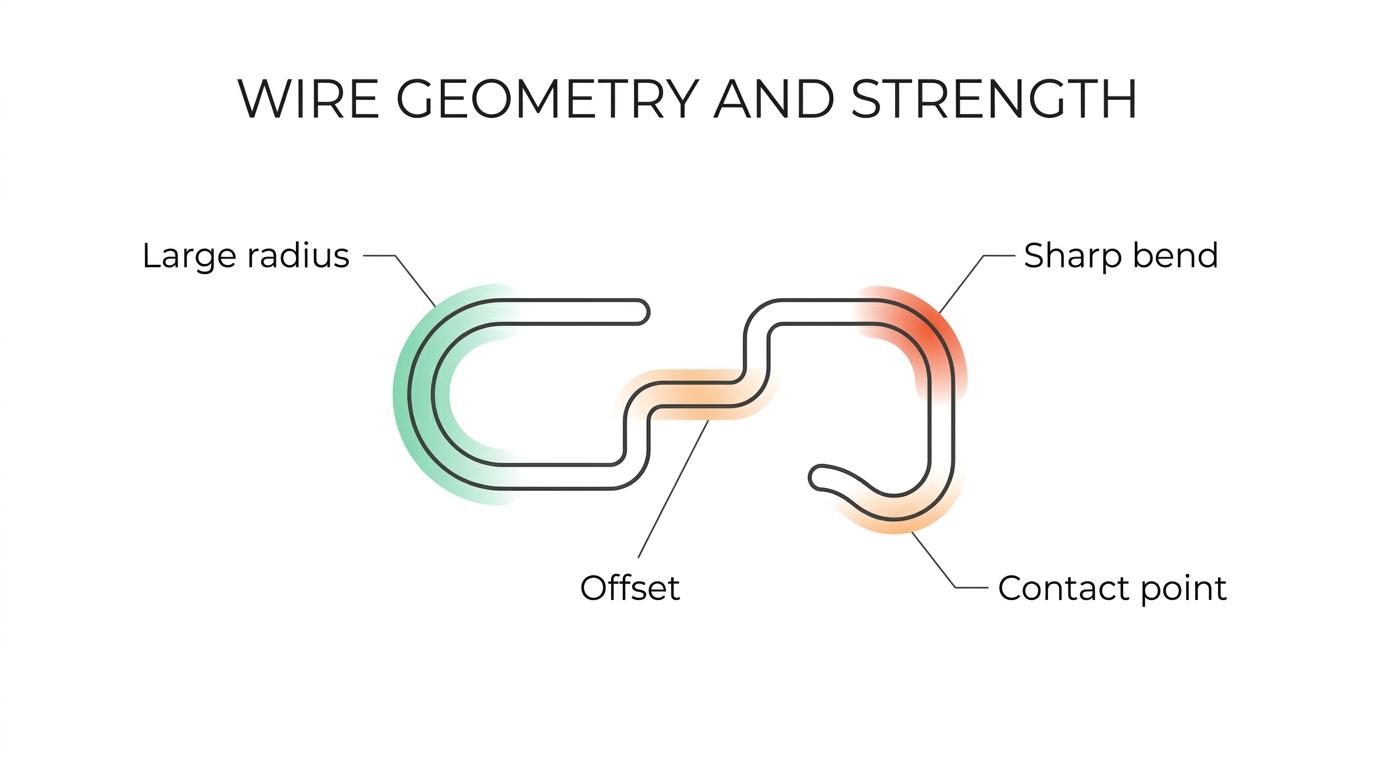
This is why shape can either protect strength or work against it. A generous bend radius can distribute stress and reduce the chance of surface cracking. A very sharp bend can create a weak spot even before the part ever enters service. If that spot is then loaded repeatedly, fatigue resistance drops fast.
Wire shaping also affects stiffness. A loop, leg length, return bend, or formed stop changes how the part deflects under load. In some assemblies, that is the goal. A spring clip, latch wire, guard, or retainer needs controlled movement. In others, too much movement means misfit, rattle, or early wear.
One more issue often gets overlooked: every bend changes the load path through the component. A simple change in bend sequence or orientation can shift force away from one feature and into another. That can improve life without increasing material size.
Material strength versus formability in wire shaping
The trade-off between strength and formability is one of the oldest realities in metal forming. Higher strength often comes with lower total elongation. That means the material may resist deformation better in service, yet tolerate less severe bending during production.
Published bending guidance from AHSS Insights makes this clear. As strength rises and total elongation falls, the minimum bend radius usually has to increase to avoid fracture at the outer surface. In practical terms, stronger material often asks for a less aggressive shape.
That has direct consequences for OEM wire parts. If a designer specifies stronger wire but keeps the same small bend radius, the part may crack during forming, develop hidden damage at the bend, or show inconsistent springback from run to run. None of those outcomes produces a stronger component in the field.
A smarter question is not, “What is the strongest wire available?” It is, “What material condition can survive forming, hold tolerance, and carry the required load after shaping?” Sometimes that answer is a lower-strength condition during forming followed by later strengthening. Sometimes it is a diameter change, a larger radius, or a geometry revision that reduces local strain.
A few design implications show up again and again:
- larger minimum bend radius
- lower allowable strain at the bend
- greater sensitivity to surface defects
- tighter need for process control
Springback and minimum bend radius in OEM wire components
Springback is the partial return of a formed part toward its original shape after the forming load is removed. In wire shaping, that small movement can make the difference between a clean fit and an assembly problem.
Yield strength, bend radius, and section size all influence springback. Higher yield strength usually means more springback. Larger bend radii can increase it as well. Thicker sections tend to resist it better. Because of that, wire components often need carefully planned overbending so the finished part relaxes into the target angle or profile.
Minimum bend radius is just as important. It is the sharpest radius that can be formed without unacceptable fracture or damage on the tension side of the bend. When teams push below that limit, they may not always see immediate failure, but the bend can still lose life, lose consistency, or drift dimensionally.
The table below shows how common forming variables affect strength-related outcomes in wire components.
| Variable | What changes during wire shaping | Likely effect on component strength | Typical design response |
|---|---|---|---|
| Higher material strength | Lower formability, more springback | Greater risk of cracking or geometry loss at tight bends | Increase bend radius, review material condition |
| Smaller bend radius | Higher outer-surface strain | Stress concentration and lower fatigue life | Open the radius or change wire size |
| Larger wire diameter or section size | More resistance to deformation | Better stiffness, though forming loads increase | Confirm tooling capability and bend allowance |
| More bends in a compact space | More cumulative tolerance stack-up | Misfit can shift load into one feature | Control bend sequence and datum strategy |
| Repeated deflection in service | Cyclic stress at formed areas | Fatigue becomes the governing failure mode | Reduce local strain and improve geometry transitions |
These are not isolated factors. They interact. A tight bend in a soft material may be fine. The same bend in a higher-strength grade may fail in production or spring back far enough to miss fit requirements. That is one reason experienced wire forming services spend so much time on both geometry review and process setup before production scales.
Tight dimensional control in multi-bend wire forms
Many OEM parts are not just one bend. They are a sequence of bends with functional relationships between legs, loops, offsets, hooks, stops, and contact points. In those parts, strength depends on dimensional control as much as raw material properties.
A multi-bend wire form can be structurally efficient because it places material only where the function needs it. It can guide, retain, support, separate, or spring-load another component while using relatively little metal. Yet that efficiency only works when the formed geometry repeats consistently from part to part.
Small angular changes can create big mechanical differences. A leg that is a degree off may preload an assembly too much. A hook position that drifts can change insertion force. A stop feature that moves can shift load into a welded joint or plastic housing. Those are geometry problems first, even if they later show up as strength failures.
This is where process capability matters. Precision CNC forming, controlled bend sequencing, and inspection around critical dimensions help keep structural performance consistent. Teams sourcing custom wire forms should look beyond nominal shape and ask how repeatability is maintained across prototypes, pilot builds, and volume production.
Three geometry issues deserve early review:
- Bend sequence: earlier bends can change how later bends land, especially in 3D forms
- Datum strategy: inspection points should reflect how the part actually locates in the assembly
- Tolerance stack-up: multiple acceptable bend variations can still create an unacceptable final fit
When stronger wire creates a weaker component
This sounds backward, but it happens often.
A stronger material can produce a weaker real-world part when the geometry was created for a softer wire. The formed shape may trap too much strain at the bend, spring back out of position, or require forcing during assembly. That forced fit can preload the component in ways the drawing never intended.
Take a retaining wire that must snap into a groove repeatedly. If the bend radius is too sharp for the chosen material, the part may survive forming but lose fatigue life at the same spot that sees every installation cycle. A small change in radius and leg length may outperform a pure material upgrade.
The same pattern appears in wire guards, supports, and welded frames. Designers sometimes increase tensile or yield strength expecting a durability gain, yet the new material creates more springback and wider dimensional variation. Once the part no longer seats consistently, the assembly starts carrying eccentric loads. Performance drops, even though the metal is technically stronger.
Warning signs usually show up early if teams know what to look for:
- cracked or whitened bend surfaces
- angle drift after forming
- variable insertion force
- parts that need manual tweaking to fit
- fatigue failures starting at the outer bend surface
Bend geometry and service conditions must be matched
Strength in use depends on how the part is loaded after shaping. A wire component carrying static load has a different risk profile than one that flexes thousands of times, sees vibration, or acts as a spring element.
That means design review should connect the formed geometry to the real service condition. Is the part mainly a support? A locator? A clip? A torsion feature? A guard? Those are different mechanical jobs, and they may call for very different radius, material, and tolerance choices even when the outer shape looks similar on paper.
In repeated-motion applications, local strain control often matters more than headline strength values. In structural support applications, section size and load path may matter more than spring properties. In fit-critical assemblies, springback compensation and dimensional control may be the deciding factors.
What OEM teams should share with a wireform manufacturer before prototyping
Early technical input tends to save time here. The most productive conversations happen before tooling paths and print tolerances harden around a geometry that was difficult to form from the start.
When a design is headed for prototype or production, it helps to provide more than a drawing. A capable supplier can give better guidance on bend radius, springback compensation, and process fit when the application details are clear.
Useful inputs include:
- Service load: static, cyclic, shock, or vibration
- Deflection requirement: whether the part must flex, return, or stay rigid
- Material target: alloy, temper, hardness, coating, or corrosion need
- Critical dimensions: functional datums, contact points, and fit features
- Assembly method: manual insertion, robotic install, welded assembly, or captured placement
- Volume plan: prototype, short run, bridge production, or high-volume demand
Those details help a precision wire forming partner evaluate whether the current geometry is workable, whether the bend radius should be adjusted, and whether the material choice supports both manufacturing and field performance.
In many cases, the best improvement is modest: a slightly larger radius, a longer straight between bends, a different wire diameter, or a revised tolerance tied to how the part actually functions. Those changes can protect strength, improve repeatability, and reduce assembly variation at the same time.
When wire shaping is treated as a structural design variable rather than just a manufacturing step, OEM components tend to fit better, last longer, and perform more predictably under real loads.
Keywords:
wire shaping