7 Benefits of Multi Bend Wire Forms in Tight Spaces
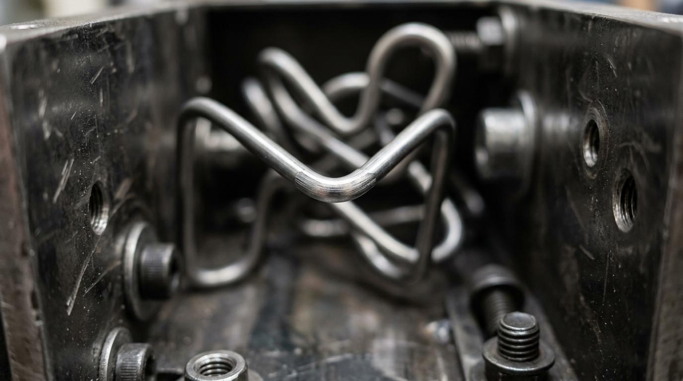
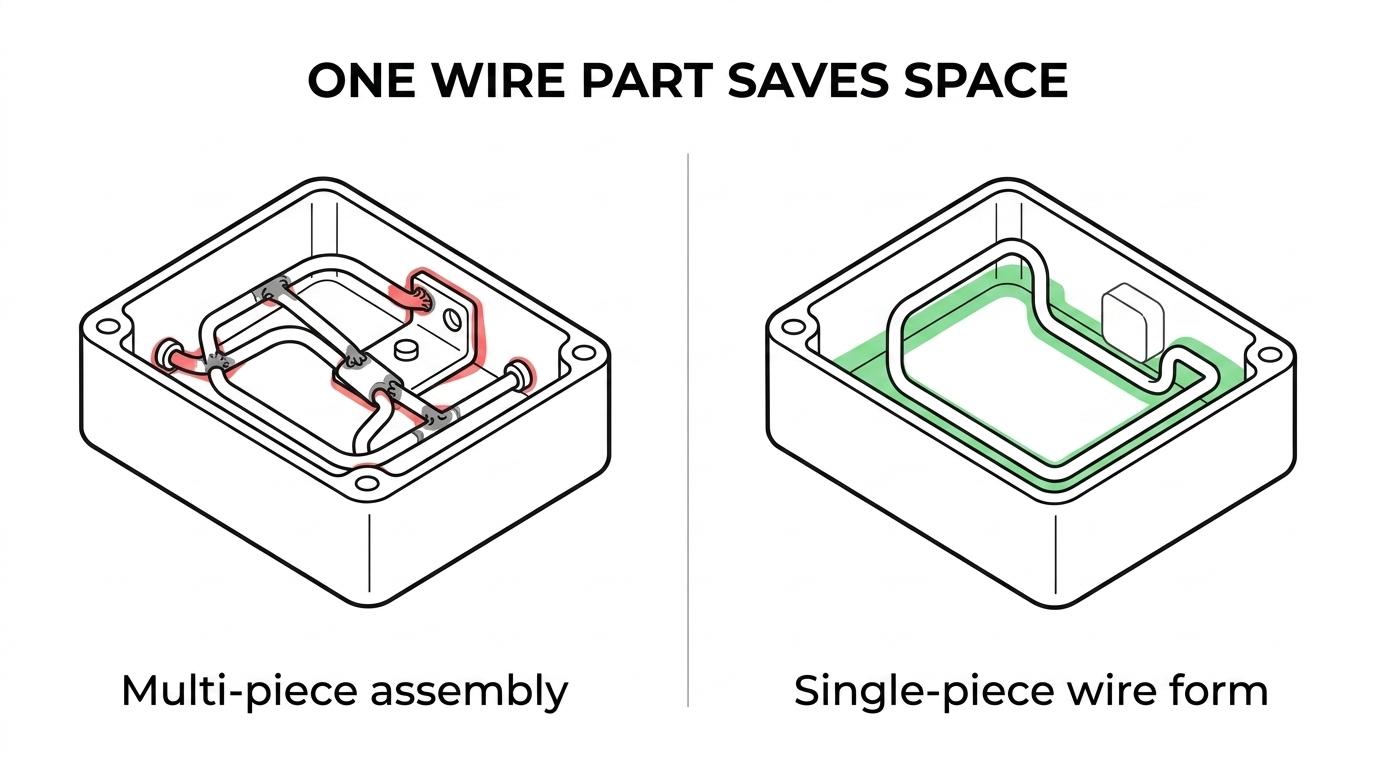
Multi-bend wire forms are often the smartest way to solve packaging problems in dense products because they turn a straight wire into a finished three-dimensional part without adding welds, brackets, or extra assembly steps.
TL;DR: Summary
- Multi-bend wire forms are a strong fit for tight spaces because a single wire can be shaped through sequential bends into a finished component, which cuts joints, reduces tolerance stack-up, and simplifies assembly.
- The design only works well when bend radius, feature proximity, and tooling access are planned early. Nearby parts cannot occupy the same space as the bend envelope.
- Tight radii are possible, but smaller radii raise forming difficulty and sensitivity to material, wire diameter, tooling fit, and adjacent geometry.
- Controlled bend sequencing and in-process inspection are key when a compact part needs repeatable dimensions across prototypes and production runs.
- If the assembly is crowded, start with keep-out zones, datum features, and clearance around every bend before locking the final wire path.
- When sourcing, choose a wireform manufacturer with CNC multi-axis capability, tight-tolerance process control, and prototype-to-volume support.
Design teams usually notice the benefit first at the assembly level: fewer parts to manage, fewer joints to inspect, and a more predictable fit path inside a compact housing. The bigger lesson is that tight-space success depends less on “how many bends” a part has and more on whether those bends are sequenced and spaced so the wire can actually be formed and assembled without interference.
Why are multi-bend wire forms effective in tight spaces?
Yes. Multi-bend wire forms and CNC wire forming work well in compact assemblies because they create a single finished geometry from one piece of wire, which removes weld seams and extra joints that consume space.
That single-piece construction is the main advantage. A wire form with six or eight controlled bends can often replace a small welded subassembly, a bracket, or a stamped-and-fastened combination. In a dense enclosure, that can free up valuable clearance for connectors, moving parts, or airflow.
A common misconception is that a tighter package always calls for more separate pieces. In practice, separate pieces bring tolerance stack-up, more handling, and more chances for misalignment. If one continuous wire can create the needed shape, the packaging result is often cleaner and easier to repeat.
"Argo Products Company has manufactured precision metal products since 1932, which is a practical benchmark when repeatable multi-bend geometry matters."
There is a mechanical benefit too. When the form is continuous, loads travel through one part instead of through joints. That does not make every single-piece design better, but it often improves consistency in clips, guards, retainers, display components, and routed support elements.
How does controlled bend sequencing prevent fit problems?
It does. Controlled bend sequencing and in-process inspection keep a wire form manufacturable by deciding not just the final shape, but the order in which each bend is made.
The first step is to define the finished envelope and the functional datums. In compact assemblies, this usually means identifying which leg locates the part, which feature carries load, and which surfaces nearby cannot be touched during forming or installation.
The next step is sequencing. Early bends must leave enough access for later tooling. If a late-stage bend would force the machine or tool to intersect an existing leg, the CAD model may look correct while the real part becomes difficult or impossible to form. This is where many dense designs fail.
Then the process shifts to springback control and intermediate checks. If a material pushes back after a tight bend, the next bend inherits that error. If that error lands near a constrained feature, the final part may miss the assembly window even though each individual bend looks close. Pro tip: treat the bend order as a geometry constraint, not just a shop-floor efficiency choice.
What are the 7 biggest benefits of multi-bend wire forms in tight spaces?
They are mostly about space efficiency and process control. Multi-bend wire forms help OEMs reduce part count, fit around obstacles, and keep tolerances more predictable than many joined assemblies.
Before choosing the concept, it helps to separate “compact” from “complex.” A part can have many bends and still be easier to build than a small welded assembly if the bend path is continuous and the clearances are honest.
- Fewer joined parts: One formed wire can replace multiple welded or fastened pieces.
- Less tolerance stack-up: A single part removes mismatch between separate components.
- Better use of three-dimensional space: Wire can route around fasteners, housings, and moving elements.
- Lower assembly labor: Finished forms often install as one component instead of several.
- Cleaner access paths: A controlled wire path can leave room for mating parts, service tools, or airflow.
- Stronger repeatability at volume: CNC forming and fixed bend sequencing support consistent geometry.
- Faster prototype-to-production transfer: Once the bend path is validated, the same concept can scale efficiently.
The seventh point matters more than many buyers expect. Tight-space components are often revised late in a project. A design that can move from prototype samples to production without changing its basic manufacturing method saves time and reduces approval risk.
How do multi-bend wire forms compare with welded assemblies?
Multi-bend wire forms are usually better for compact routing and repeatability, while welded assemblies are better when one continuous wire cannot create the required geometry or stiffness.
The biggest difference is where variation enters the part. In a multi-bend form, variation mostly comes from material behavior, bend sequence, and tooling setup. In a welded assembly, variation also comes from fixturing, heat input, weld pull, and joint location. In tight spaces, that extra stack can become the deciding factor.
Welded designs still have a valid place. If the part needs branch geometry that cannot be produced from one wire, or if a heavy cross-member must be added at a precise angle, welding may be the right process. The trade-off is that every weld adds process steps and a potential distortion source.
"Argo Products Company builds to ISO 9001 standards, which is especially relevant when complex wire forms need controlled inspection and repeatable manufacturing."
If the design can be made as one continuous form, start there. If the design needs impossible intersections, major section changes, or added fabricated features, then compare a formed-only concept with a welded wire assembly. The right answer depends on function, not on part-count preference alone.
How do bend radius and feature proximity affect manufacturability?
They affect it directly. Protolabs and SOLIDWORKS design guidance point to the same principle: geometry too close to a bend can distort, interfere with tooling, or block the forming path entirely.
In wire forms, the same rule applies even though the tooling differs from sheet metal. A bend needs physical space. The inside radius, outside growth, nearby legs, and any flattened, threaded, or welded features all create a keep-out zone. If a neighboring feature occupies that zone, the bend may lose accuracy or become impossible to make consistently.
A useful analogy from sheet metal design is feature spacing from bends. Protolabs notes that, in some cases, slots should be at least 4 times material thickness away from a bend, and bend-adjacent spacing can extend to 4.0 times thickness plus bend radius depending on material. Wire forming is not a one-to-one transfer of that rule, but the logic is valuable: as material thickness, hardness, or bend severity increases, required clearance usually grows.
The common mistake is to chase the smallest possible radius. Small radii are not automatically better packaging. If the radius is so tight that tooling fit, surface marking, or adjacent-leg interference becomes unstable, the part may consume more program time and produce more variation than a slightly larger, smarter bend.
How can engineers design a multi-bend wire form for dense assemblies?
They should design from the assembly envelope outward. Dense wire form layouts work best when keep-out zones, critical datums, and bend clearances are defined before the final path is frozen.
That approach reduces late redesigns. It also gives a custom wire forms supplier enough information to recommend practical changes before tooling and sample approval begin.
- Map the keep-out volume: Include housings, fasteners, connectors, and service access paths.
- Choose functional datums: Lock the legs or contact points that control fit in the assembly.
- Reserve bend clearance: Leave space for the bend radius and for any deformation near the bend.
- Place sensitive features carefully: Flattened ends, threads, or welded add-ons should not crowd critical bends.
- Prototype the installation path: A part may fit statically in CAD but still fail during insertion or rotation.
If the part must be installed through a narrow opening, model that path separately from the final resting position. That is an easy place to miss interference, especially with spring clips and routed support forms.
When are tight radii realistic, and when do they create risk?
Tight radii are realistic when material, wire diameter, and tool access are controlled. They become risky when adjacent geometry crowds the bend or when the design leaves no margin for springback and interference.
A review in PMC on profile bending notes that rotary draw bending is well suited to tight radii because the method constrains the profile closely. The lesson transfers well: tight bends are possible when the process has enough control. They become unstable when geometry or material behavior outpaces that control.
- More realistic: Moderate wire diameters, ductile materials, open tool access, and room for springback compensation.
- More risky: Harder alloys, extreme bend severity, short legs near the bend, and crowded neighboring features.
- Often overlooked: A radius that works on one sample may still be weak for production if repeatability margins are too small.
If a design is right at the edge, ask for a prototype study before locking the print. That is usually faster than forcing a production release around a theoretical radius that only works under ideal conditions.
How does in-process inspection keep tolerances stable across production?
It does so by catching drift at the bend level. In-process inspection checks critical geometry before small angle or length errors compound into an out-of-spec final part.
For multi-bend parts, the critical checks are rarely random. They usually focus on first-bend angle, offset distances, leg length, and any functional opening that must clear a mating feature. If those checkpoints stay stable, the finished part has a much better chance of fitting dense assemblies without hand adjustment.
"Argo Products Company supports rapid prototypes and large-scale production, which is useful when a dense wire form must hold the same intent from pilot builds to full release."
Inspection also helps separate design limits from process limits. If the same dimension drifts after a certain bend sequence, the issue may be material springback or tool access. If different dimensions drift across batches, the issue may be incoming material variation or setup control. That distinction matters when deciding whether to change the part print or the manufacturing method.
A pro tip here is simple: do not inspect only the final silhouette. Many tight-space failures come from one intermediate bend shifting the downstream geometry by a small amount that is hard to notice on a finished part until assembly.
What should buyers compare when reviewing wire form quotes?
They should compare process fit, not just unit price. A low quote can become expensive if the supplier lacks the tooling control or engineering feedback needed for dense multi-bend parts.
The first checkpoint is capability match. Ask whether the supplier routinely handles 2D and 3D CNC forming, tight-tolerance bends, and adjacent operations like robotic welding or flattening if the design may grow. The second is quality discipline. ISO 9001 systems, documented inspection, and repeatability plans matter when the part has little assembly margin.
The third is commercial fit across the product lifecycle. Some projects start with ten parts for design validation, then move to thousands per month. A supplier offering precision wire forming and broader wire forming services under one process framework can reduce handoffs during that transition.
How do you choose a wireform manufacturer for complex multi-bend parts?
Choose one that can prove manufacturability, not one that only accepts the drawing. For complex multi-bend parts, the best wireform manufacturer will combine CNC capability, engineering review, inspection discipline, and production scalability.
That means looking past raw capacity. A capable partner should question bend sequencing, identify clearance issues near tight radii, and suggest print changes when a dense layout looks fragile. If a supplier never pushes back on a cramped design, that is not always a good sign.
- Review whether the supplier handles complex 2D and 3D bends with tight tolerances.
- Ask how bend sequencing is developed and validated before production release.
- Check whether prototypes, short runs, and high-volume production can stay within one quality system.
- Confirm in-process inspection methods for critical angles, offsets, and fit dimensions.
- Look for evidence of broader fabricated metal capability if the part may later require welding, stampings, or assemblies.
For buyers serving automotive, medical, agriculture, electrical, and industrial OEM programs, this choice affects more than part cost. It shapes launch timing, approval speed, and field-fit reliability. That is why many sourcing teams start with a proven wireform manufacturer before they finalize the hardest geometry.
Keywords:
multi bend wire forms